FSJ vacuum routing can be daunting to look at. Here's a quick rundown on routing for a mid-80's FSJ. Different model years used slightly different vacuum routing. See links at the bottom for a great site on vac diagrams for various model years.
Here's a large, hi-res diagram that is color coded to make it a little easier to distinguish between different vacuum sources. We'll dissect this thing piece by piece to make it easier to figure out.
 |
| Color-coded FSJ Vacuum Diagram for V8 |
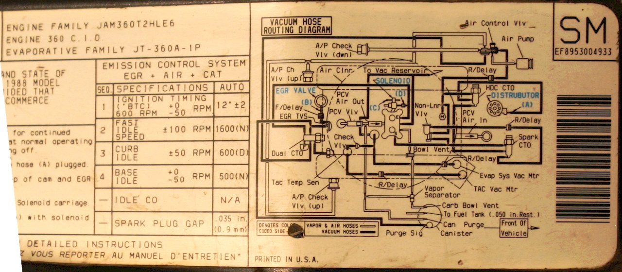
There are a few minor differences between 85 and 86+ so here is an underhood vac diagram for 88 to reference for some stuff. Big thanks to
Tom 'Oljeep' Collins for putting all these diagrams (and more) in one place!
88_FSJ_Vacuum_360.jpg
Let's step through the diagram to understand it better.
Vacuum Spark Advance
Spark advance is based on engine temperature as follows:
- Under 160°F: mixture of manifold and vacuum advance
- Over 220°F: manifold vacuum
- Otherwise: ported vacuum
Knowing how the system behaves, let's trace the vacuum hoses from the distributor backwards.
The distributor vacuum hose traces back to the middle "output" port of the HDC CTO (Coolant Temperature Override) vacuum switch; that's the CTO on the thermostat housing. The middle of these type of CTO's is the "output" and based on temp, it switches between one of the two "inputs".
 |
| Spark advance vacuum routing |
If the engine is too hot, above 220°F, it draws from manifold vacuum. Why? Because the theory is that this will bump up the idle and thus cool the engine down. Does this work? I doubt it.
 |
| Hot (>220°F) spark advance vacuum routing
|
If the vehicle is below 220°F, the "input" selects the Spark CTO switch's "output". The Spark CTO selects a vacuum source for cold or warm operation.
 |
| Normal spark advance vacuum routing |
If the vehicle is warm, above 160°F, it simply selects ported manifold vacuum as the source for vacuum advance. Easy enough.
 |
| Normal temp, spark vacuum advance routing
|
When the engine is cold, below 160°F, the engine gets a mix of manifold and ported vacuum. The device that controls the vacuum signal during cold operation is the Non-Linear Vacuum Regulator. It basically just limits the vacuum signal going to the vacuum advance.
 |
| Cold temp, NLVR vacuum routing
|
Ok, so that takes care of the entire spark advance system.
Simplify Vacuum Advance Routing
 |
| Simple FSJ Vacuum Routing |
You can simply all this if you so choose. First, remove the NLVR. Where it "taps into" a vac line, replace the T with a straight adapter or run new line.
What you end up with is the Spark CTO gets Manifold vacuum when cold, and ported when hot. This is how the earlier model FSJs were "wired".
You can also ditch the high temp (HDC) CTO. Run the Vac advance line direct to the Spark CTO "output" (middle). Remove the T fitting for the HDC CTO that goes to manifold and replace with straight or run new line.
Make sure you preserve a manifold vac signal going to the power valve!! (or else it will always be on!) This greatly simplifies the spaghetti. You now have one CTO where you used to have a 2 CTOs and an NLVR.
EGR Vacuum Control Routing
Let's move on to the the EGR system. It's operating is also based on temperature. If the EGR is enabled, it only operates on part throttle load. Not full throttle, and not lightly loaded part throttle or idle. The EGR is only enabled when both the engine coolant temperature and incoming air charge are warm.
Starting at the EGR itself, it is ultimately sent a ported EGR signal from the carburetor. But that signal only makes to the EGR if the air drawn into the motor is warm, as determined by a sensor on the side of the air cleaner housing called the TVS (Thermal Vacuum Switch). When it's warm, it lets vacuum through. When it's cold, it blocks vacuum signal, disabling the EGR.
 |
| EGR Vacuum Control |
The signal also won't make it to the EGR if the engine coolant temperature is too low, as determined by one half of the Dual CTO. It's just like the CTOs used in spark advance, but they packaged two CTOs in one device.
Also, there's often a delay valve inline between the EGR and the TVS so that the EGR comes on gradually after a short delay. However, one service bulletin fix for pinging is to remove this. So you may not have it. That's the EGR system.
AIR System Vacuum Routing
Let's look at the AIR system. AIR stands for Air Injection Reaction and it injects air into the exhaust manifolds under certain conditions to oxidize unburned fuel and at other times into the catalytic converter to aid its operation.
The source of this air is the AIR pump. The air goes to a diverter valve (AIR Control Valve) that sends air to the manifolds or to the catalytic converter, based on engine temp as well as engine load.
Under acceleration the signal goes away which diverts air to the cat (to address the vehicle running rich). When cold or under cruise, the air is sent to the manifolds to further oxidize the outputs of combustion.
On 86+ FSJs (see below) the AIR Control Valve also includes a valve to allow or shut off the flow entirely; when the vehicle starts up, it turns on the valve with manifold vacuum. During acceleration, when manifold vacuum drops, the reverse delay keeps the system on.
 |
| 86+ FSJ Air Control Valve Vacuum Routing |
The air control valve diverter is controlled by manifold vacuum. When the vehicle is cold, air is sent to the manifolds, when hot, to the catalytic converter, but only under heavy load (low manifold vacuum).
 |
| AIR system vacuum routing |
And that's it for the AIR system.
Thermal Air Control
The Thermal Air Control (TAC) system operates the valves on your air cleaner snorkle to regulate the intake air temperature.
When the engine is on, manifold vacuum is held and applied to the main valve in the snorkle; when the engine is shut off, the valve closes, helping to prevent evaporation of fuel, presumably.
A TAC sensor, in essence a thermal vacuum switch, tells the second valve to select hot air drawn across the exhaust manifold through the silvery corrugated downpipe that you probably lost years ago or, once the engine is warm, from cooler outside air, through the corrugated black tube going to the front of the engine bay near the battery if you didn't lose that too.
 |
| TAC vacuum routing |
The check valve holds vacuum on the main valve motor (evaporative system motor) to keep the valve open at all times while the engine is running.
Vacuum Brake Booster
And that's pretty much it. You also have a giant vacuum tube going from the front manifold brass fitting to the brake booster.
Heater and 4x4 Control
There's supposed to be a vacuum signal going to the round ball -- a vacuum reservoir for your 4x4 and heater.
Cruise Control
And also vacuum to the black coffee can on the passenger side-- your cruise control reservoir. Those aren't shown on the diagram.
PCV, Bowl Vent, Gas Tank Vent
The diagram above shows your PCV (Positive Crankcase Ventilation) routing, bowl vent and purge valve routing, and gas tank vent routing. The carbon canister opens up to allow the carburetor to draw fuel vapors in by way of the purge valve, operated by ported vacuum. Under part throttle heavy load, the carburetor sucks some fuel vapor out of the canister.
 |
| PCV, Bowl Vent, Carbon Canister |
Simplification
Added 01/04/08
Thanks to
Strider on IFSJA BBS for providing the graphic of a simplified spark advance. I did this on my rig some time ago for testing, and it seems to work fine. Basically you're eliminating the 2nd CTO and the NLVR. This really cleans up the spaghetti.
Further Information
The best collection of FSJ vacuum diagrams has to be
Tom 'Oljeep' Collins' website, hands down. He also has great electrical schematics for various years and myriad other reference material.