Showing posts with label FSJ Tech. Show all posts

Tuesday, May 3, 2016

Front Door Speaker Install

from jedi.com
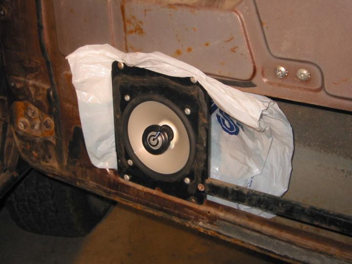
My Alpine deck and 5" Boston Acoustics should have sounded decent but even for small speakers, they lacked the low end response. Why?

In large part because the OEM speaker installation method leaves much to be desired. 

Speakers are mounted on flimsy sheet metal that partially spans a giant hole in the door. 

To get more out of your FSJ's stereo, read on.

Monday, April 25, 2016

FSJ Cowl Vent Screens


If you've owned an FSJ during autumn, you know that the cowl fresh air intake is a magnet for leaves, twigs, and other debris that end up clogging your fresh air vents and drain holes, leaking water into your FSJ and rusting it from the inside out.

Several years ago, I implemented a low cost solution that's easy to install and aesthetically pleasing.

First, remove the vent grill. Lift the engine hood and then remove 7 screws and the windshield washer nozzles and lift out the cowl vent grill. The grill measures about 48" x 6".

A trip to the local home improvement store yielded several viable options. Of those, I selected these plastic gutter screens as one of the lowest cost options. They've held up well for 10 years so far.

Next, use the grille as a pattern and mark on the rain gutter covers. Two are required to cover the entire cowl vent. Position the cover to hide the thick bars of the gutter cover. Measure twice, cut once! 

Gutter screens
Each covers half the cowl vent
Measure twice and mark
Cut, test fit, trim
Then cut out the gutter covers with strong, sharp scissors, metal snips, etc.  Test fit and trim so that the guard is slightly smaller than the grille area. 

Now test fit on the cowl to make sure the guard is not blocking the cowl grill's tabs that fit into slots nearest the windshield. Trim as needed.

Remove four rubber pieces against which the grille rests. Note where they were positioned. You'll put them back on later once the guard is in place, using some adhesive.
Reattach bumpers with adhesive
I used these #8 self-tapping screws
It is easiest to attach the guards directly to the Jeep's body, rather than to the cowl grill. I used #8 self-tapping sheet metal screws with wide, flat phillips heads. Before you start screwing in the screen with these screws, mark locations for the screws where they'll be hidden by the grill.

It works great!
Next, drill/drive in the screws, starting at the center and working outward. I used two screws in the middle, at the edges, and one on either side of the washer arms. That's enough to keep it in place and sufficiently tight against the surface of the intake.

What about the window washer nozzles? You could cut a hole for the stock nozzles which suck by modern standards. And, a little bit of stuff might get into the cowl. You could install modern hood nozzles, but that requires cutting up your hood. I tried this but be sure to measure carefully. Finally, wiper arm nozzles are an option, but may require cutting a small hole in the cowl screen to route the tubing.

The final step is to reinstall the cowl vent grill. Then, no more fall leaves entering your fresh air vents! Hope you find this helpful. I'm very glad I did this mod and wished I'd done it even sooner.

Tuesday, April 19, 2016

Replacing an A727 Reverse Servo

I knew what was wrong with the A-727. The reverse servo piston had cracked.

The Shimniok daddy-daughter Moab trip was coming up at the end of March.

I just had to get my rig back on the road and fast!

Which New Piston?

Unlike the stock, cast material, billet aluminum isn't prone to cracking, making them popular among the Mopar drag race crowd who also prefer 1-piece servos without the stock inner spring that cushions reverse engagement.

But surprise! The Jeep isn't a dragster. Fortunately, Randy J (mrrandyj) sells both 1- and 2-piece piston kits for 727. He's a good guy, easy to work with, and happy to share his considerable knowledge.

Real engineering, the kind that takes obsessive dedication and doesn't fit in a sound bite or ad slogan, is what Randy put into his awesome products.

The kit includes the piston, a new piston spring, and a beefy spring retainer, eliminating all the common reverse servo issues. You reuse the stock pin and inner spring.

Read on for the disassembly and reinstallation...

Tuesday, March 15, 2016

Diagnosing 727 Reverse Problems

Chrysler A727, picture from Novak Adapters
Last we left off, I was scrambling to get the rear brakes done in time for the Mosquito Pass run. The parts arrived quickly and I did the brake job with time to spare.

One adjusts the rear drums by driving in reverse and pressing the brake, which activaties the automatic adjusters. I did this a few times and then...

Disaster

I did this a few times and was almost done, then ... no reverse! Nothing. Uh oh.

With a sinking feeling I drove home. Violet and I would be passengers on Mosquito Pass.

Transmissions are a final frontier for me: dark, arcane magical boxes of wonder, their inner workings a mystery wrapped in an enigma, enshrouded in a big WTF?! Well, here's what I did next...

Thursday, October 4, 2012

Cowl Vent Mod Keeps Leaves Out


If you've owned an FSJ through any autumn season and parked under a tree, you know that the fresh air box intake, right in front of the engine hood, draws in twigs, leaves and fall debris like some kind of giant tree magnet.


So after 10 years of ownership I finally fixed the problem. I wanted a solution that was cheap, good looking, and easy to install and which would keep out all sorts of leaves, twigs, seeds, and so on. I also had to upgrade the windshield washer squirters but I'll tell you about that later.

I started by removing the vent grill. You lift the engine hood and then remove 7 screws and the windshield washer squirters and lift the grill up back and out. Then I measured the cowl vent and it works out to about 4'x6". 


A trip to Lowe's turned up several viable options. Rolls of aluminum screen, (for screen door repair) are about $8/roll with vinyl less but figured the vinyl would tend to rip and sag. In the rain gutter aisle I found covers of aluminum mesh, in a 5-pack, 3'x6" for under $5 but I felt it was too coarse to keep out the materials from our tree. Lastly I found plastic cris-cross guards with screen for about $1.80 each which I think will stand up well so I chose these.

Next step, use the grille as a pattern and mark on the rain gutter cover. Position the cover so that the thick bars of plastic don't show and so that the guard is covering half of the grille so that you can use two guards total.

Use the grille from the Jeep as a pattern

Position to try and hide the thick bars
Then, use a pair of scissors or metal snips or whatever is convenient to cut out your shape and test fit with the grille so that the guard is slightly smaller than the grille area.

Once marked, cut out with snips, etc.

Use two guards to cover each half, meet in the middle
Now test fit on the cowl to make sure the guard is not covering the slots nearest the windshield into which the grill tabs fit. You'll need to remove four rubber pieces against which the grille rests. Note where they were positioned. You'll put them back on later once the guard is in place, using some adhesive.

Rubber grille rests
The plan is to affix the guards directly to the intake box, not to the grill. I found that Lowe's is now selling some new self-tapping sheet metal screws with extra wide, extra flat phillips heads (very similar to the oem screws used to hold on the grill). I got a box of these in the #8 size.

These screws work well to attach the guard
If you're clever you will determine before you start drilling in screws, where to place those screws so the grill completely covers them for a more cosmetically appealing result. I didn't think that far ahead.

Now you just drill in screws, perhaps starting at the center and working outward. I used two screws in the middle, at the edges, and one on either side of the washer arms. That's enough to keep it in place and sufficiently tight against the surface of the intake.

Now you just install the grille. This mod has been working great since the fall of 2007 as you can see from the pic below. Wished I'd done this when I first got the Jeep.

Take that, pesky leaves!
The last thing to note is that the windshield washer squirters are obstructed by this material. You can cut out the guards accordingly. Instead, I upgraded to modern hood-mounted squirters.

Tuesday, October 2, 2012

New Vapor Canister for FSJ

Here's an option for replacing your old AMC vapor charcoal canister with a new one. You can source a 1993 Jeep Grand Cherokee, such as from http://www.rockauto.com as pictured (Wells p/n 4B1273 pictured or Standard p/n CP3045)
image from
www.rockauto.com

To work with the carburetor, I had to drill out the right side port (the one with the X).

I should mention the truck experienced some lean conditions after installation, particularly on throttle opening and I didn't get around to fixing it. Some carburetor adjustment will be required, I think.

The vehicle is now running electronic fuel injection and the problem has gone away as far as I can tell, so perhaps the Motorcraft 2150 carburetor I was using just needed some tweaking.

I was already running lean jets (#52 I think versus the #55 stock); maybe the old canister permitted less air flow than the new one. That is only an issue when ported vacuum increases to open up the purge valve. One might be able to restrict the airflow out of the new canister.

Monday, August 20, 2012

GM TBI Ignition Wiring

A few days ago I wired up the GM TBI system to my ignition system. My Grand Wagoneer uses the Duraspark ignition module, Duraspark AMC distributor, and an MSD Blaster 2 can coil.

Here's how I wired the TBI, based on information from Binder Planet and other sources.

Sources:


Original Wiring

The OEM wiring for the Duraspark is shown below where the ignition module has a two-pin connector and a four-pin connector. 


Two-pin connector:

  • Yellow wire is hot when the ignition switch is at ON or START positions. Powers the module.
  • Green wire is hot when the ignition is at START position. Tells module to retard timing at startup

Four-pin connector

  • Violet and Orange wires are from the distributor pickup coil
  • Black wire is the pickup coil ground
  • Green with tracer (stripe) is the coil negative terminal; the module controls spark with this wire

Notice that a ballast resistor is used to drop the coil voltage to 9V when the vehicle is running (ON), but this resistor is bypassed with a 12V signal from the starter solenoid when cranking (START).

GM TBI Wiring

The GM TBI system I'm installing uses an 8-pin ignition module. The 8-pin module has two pins for the distributor pickup coil, P and N, a connection for power, "+" (hot in START and ON), a negative coil connector, "C", a ground, and four wires that connect to the ECM. 

GM HEI 8-Pin Ignition Module Wiring Diagram for TBI
The GM system expects a more modern coil as well, one that is powered by 12V at all times versus the OEM coil that needs 9V during regular running and 12V at start.

Duraspark to GM 8-Pin HEI Wiring

Combining these two diagrams, that is, replacing the Duraspark Ignition Module with the GM HEI 8-Pin Ignition Module, eliminating the ballast resistor to give the coil 12V at all times, we get the following:

Replacing the Duraspark module with GM 8-Pin HEI module
  • GM 8-pin module P pin connects to FSJ Light Blue (connects to distributor Violet)
  • GM N pin to FSJ White (connects to distributor Orange)
  • GM module + (Pink with trace) to FSJ Yellow wire (Duraspark power, ON, START) 
  • GM Pin C (Green) is connected to FSJ Green w/ Trace, to the negative coil. 
  • GM ground is connected to distributor ground, FSJ Black. 
  • Pins G, B, R, E go to the ECM, a subject for another article.

FSJ Duraspark wire colors varied across the years. Hopefully I've provided enough information for you to figure it out for your particular Duraspark model.

Installation

I removed the Duraspark module off the FSJ. For now, I wanted to re-use the OEM Duraspark Ignition Module connectors. Later I will convert to Weatherpack connectors. 

I cut a set of connectors off of one of my dozen spare modules that I'll never need again. I spliced the wires from these connectors to the GM 8-Pin HEI module and then plugged everything in.

Wire colors on different modules vary. These connectors use Red for module power, White for start (not connected), Black w/ Trace for ground, Green for Coil negative, Violet and Orange for Pickup coil.

GM 8-Pin HEI Ignition Module is
wired into OEM connectors
On the CustomEFI kit I bought a long tim ago, much of the wiring complexity is simplified as it comes with a really simple to use harness. For example, the red wire above connects to a relay or two, the computer, and the module already. All I have to do is hook up the red wire to the FSJ yellow providing power when the ignition switch is in ON or START positions.

Wire Splicing Tips

For a high quality, reliable splice, I used solder, heat shrink, and automotive butt connectors (blue or red as appropriate for wire gauge). First, I carefully cut off the blue/red case with a utility knife; a cut lengthwise to split the case in half and push the metal connector out (you can buy these connectors without the case, too). I cut a length of heat shrink tubing slightly longer than the butt connectors and slid it over one of the two wires to be joined. I stripped the wire ends, dipped them in flux paste, then inserted and crimped them into the butt connector. Next, I soldered the butt connector and wires with rosin core solder. Finally, I slid the heat shrink over the joint and heated it up (a lighter works but I prefer a heat gun). And, voila, a highly reliable, soldered, insulated wire splice.

Monday, August 13, 2012

Saginaw Power Steering Pump Rebuild

saginaw power steering pump
Saginaw power steering pump
If your Saginaw power steering pump is no longer working well or is leaking, save about $50 and rebuild it yourself. Here's a DIY guide on how to rebuild your PS pump.

These pumps are found in one of myriad older cars from the 70's and 80's: Buicks, Cadillacs, Chevrolets, Pontiacs, Oldsmobiles, GMCs, Volvos, Saabs, Chryslers, AMCs, Jeeps.

Tools Required


You need some basic mechanical skills, a little time, and either this $15 rebuild kit P/N 7910 or this $12 seal kit P/N 7918 (below). You can get these from various auto parts stores. Other brands are available.

Note: if your shaft bushing is worn, make sure you get a kit with the shaft bushing. Otherwise, the Powercraft 7918 seal kit is cheapest.

saginaw power steering pump repair kit
Powercraft P/N 7918 power steering repair kit
You'll need at least some of these tools:
  • Impact wrench for removing mounting studs and fittings 
  • Combination wrenches for reinstall to prevent stripping studs 
  • Thin screwdrivers for prying 
  • A nail, scribe or punch, you'll see why 
  • The red box to the left is the kit for removing the PS pulley. 
  • Hammer for tapping out the shaft 
  • A seal puller tool will also help. 

saginaw power steering pump rebuild tools

Reservoir Disassembly


saginaw power steering pump rebuild
#1, #2 are mounting studs, #3 is the pressure fitting
Refer to the photo above. To begin disassembly, use an electric or air impact wrench with a long socket on #1 and #2, the mounting studs. They attach the case to the internal PS mechanism.

For #3 above, remove the fitting (probably did this already when you took out the pump) and use a 1" socket on the fitting to remove it. Be careful because there is a spring-loaded pressure valve that could pop out (below).

saginaw power steering pump pressure valve
Spring-loaded pressure valve
Use a power steering pump pulley remover/installer kit (available for borrowing or purchase from AutoZone, O'Reilly, etc., or purchase from Harbor Freight) I don't have any pictures of how to use this tool as they may vary. You can also have your local auto parts store remove the pulley for you.

Now place the pump in the vise (below). There is a flat spot on the snout casting, so clamp onto that. 

saginaw power steering pump rebuild
Pump in vise on snout flat spots
Use a rubber mallet and tap off the cover. Remove the magnet and clean off all the metal flakes from it (below).

saginaw power steering pump rebuild
Magnet inside the reservoir traps metal particles

Power Steering Pump Disassembly

Next, you'll need to remove the lock ring that holds the pressure plate in place. There's a hole at the bottom of the PS casting through which you can insert a nail or similar object to force the lock ring out. You can then pry it out.

saginaw power steering pump rebuild
Lock ring removal; use access hole in casting

saginaw power steering pump rebuild
Lock ring removal, another viewpoint
If it helps, you may have to press down on the pressure plate while doing the above.

saginaw power steering pump rebuild
Press down on pressure plate while removing lock ring.

Here are the parts that you've taken out so far. The lock ring, pressure plate, spring that holds the pressure plate against the lock ring, magnet, and pressure relief valve.

saginaw power steering pump parts
Left, pressure plate; center, lock ring, pressure plate spring,
Top left: stud, top right: pressure valve and spring, magnet
Inside, you'll see the pump assembly held in with a couple pins. The assembly is made up of a front and rear cover, sandwiching the eccentric housing and the vane and rotor assembly. 

IMPORTANT NOTE BEFORE YOU REMOVE ANYTHING ELSE: Find the arrows on the eccentric housing, and note whether they are positioned at the front or the back of the power steering pump. You can install the housing in the wrong way.

If you do, when you reinstall in your vehicle, you will find it extremely hard to turn the steering wheel--the pump is actually fighting against you instead of assisting you. Ask me how I know!

There are many little steel vanes that slide in and out of slots on the rotor. First, remove the small lock ring on the pump shaft holding this assembly in. And, when you tip the pump upside down to tap out this assembly be careful you don't lose any parts. When you're done you'll have a bigger pile of parts.

saginaw power steering pump parts
Disassembly of Power Steering Pump section
Finally you'll need to tap the shaft (below) from the front.

saginaw power steering pump rebuild
Tap out shaft
You'll have this pile of parts, which now includes the pump shaft and lock ring.

saginaw power steering pump parts
Power steering pump parts now including shaft
Finally everything is disassembled. Now it's time to replace all the remaining seals and reassemble. 

Power Steering Rebuild

saginaw power steering pump rebuild
Remove PS front seal with seal removal tool or screwdriver
Now, remove the front seal. You can also drive out the shaft bushing and replace that.

Replace the o-ring on the rear pressure regulator fitting (below). 

saginaw power steering pump rebuild o-rings
Replace pressure regulator o-ring
Clean the pump mechanism parts: the vanes, rotor, and rest of the assembly. Might as well oil them with ATF (or PS fluid) and reassemble them into the case with the lock pins. 

Once again, make sure the direction of rotation is correct.

Replace the large o-ring around the pump housing, and the two small and one medium o-ring on the back face (below). 

saginaw power steering pump o-rings
Add caption

PS Pump Reassembly

Reassembly is essentially the reverse of disassembly. Reassemble the pump mechanism into the reservoir, reinstall the studs, pressure valve, and fitting, etc. Reinstall the PS pump onto the vehicle, reinstall the pressure hose and return hose, fill the reservoir, and give it a try. 

If all goes well, it won't leak, and your power steering assist will be like new once again. Congratulations, you did it!

Basic Troubleshooting Tips

If it does leak, particularly around the large seal between the pump and reservoir, you might consider finding a different case at the junkyard and trying once more. That happened to me. The second time it worked great. Again if the power steering is fighting you and it's really hard to turn the wheel, you reversed the rotation of the pump eccentric housing. Time to do it all over again.

Even if you fail once or twice, in the long run, as you do this a few more times over the life of this and other vehicles, it'll get easier and you won't have to keep spending big bucks on rebuilt pumps.

Friday, August 10, 2012

On-Board Air Install

I thought I'd share everything I've done with my own OBA system to date in case it helps you out. The following is a logical diagram of the OBA system.


Hardware

Here's a diagram of the hardware layout. I'll highlight each of the main components in the following sections.


Compressors

FSJs came with York air conditioning compressors from the 70's through about 1987 or 1988. These are the go-to compressors for OBA primarily due to air flow but also because running them upright means they don't lose (much) oil. After about 1988, Chrysler switched over to a Sanden rotary compressor which are not good for OBA due to the way oiling works. But they're fine for AC.

Orientation

Normally the earlier York compressors came from the factory installed horizontally with the compressor's head on the left side of the vehicle but you can just as easily install them upright. I ran mine this way while it was still doing AC duties for a few years and it did great. How?

Take off the AC bracket, then unbolt the York from the bracket, relocate the studs from the side to the bottom, and reattach bracket to the bottom, and reinstall bracket. You may want to add some bracing as well as you won't be able to reuse the factory top brace.

Once installed vertically the compressor will (mostly) retain oil in the crankcase (the York is basically like a little engine but with a head specific to air compression). There's another conversion you can do to force it to retain all the oil, but I haven't done that yet. If/when I do, I'll let you know.

OBA, The Basic Parts

First off, let's talk about the overall system design. In TC's case, I wanted OBA for airing up tires after trail runs and I wanted a source of compressed air to run my ARB front locker (sssh, don't tell ARB because I voided the warranty by not using their $300 electric compressor). I also needed an air tank for both uses. Let's ignore the locker air system for now.

First you need fittings that convert your York to National Pipe Thread (NPT) fittings. You can source these from Kilby Enterprises, pictured below.

NPT adapter
If you add a tank, the first thing you want to do is make sure you have a popoff valve on the tank (pictured below). This is a very, very critical safety device that ensures you don't pressurize your tank beyond its limits.
Safety valve
How do you find the tank's pressure limits? Find out the maximum pressure rating when you get the tank first from eBay, or craigslist, or new from 4x4 shops. Then get a popoff valve, rated at or below the tank rated pressure, from the hardware store or an industrial supply / compressor store, or buy online at Kilby, Northern Tool + Equipment, McMaster Carr, Grainger, or various other places.

Unless you convert the York it is going to spit out a little bit of oil (less since it is oriented vertically) and you don't want that oil in your tires, do you? To prevent it, get a mini oil separator from your favorite hardware store. Mini because it'll be easier to find a place for.

Typical pressure switch
Kilby pressure switch
The other thing you need is a pressure switch (pictured above) that is matched to your system's pressure capacities. Let's say you have a 150psi tank, so you'll probably have a 150psi air safety valve, so you want your compressor to turn off before 150psi (well, at least I would think this would be best; depends on whether the pop-off releases above 150 or right at 150)

You can get these switches from hardware stores, McMaster Carr, Northern Tool, etc., or you can get a smaller, simpler one from Kilby. I got mine from an industrial supply shop. These switches are designed to turn on the compressor at a low pressure setting, and turn off at a high pressure. Ideally, the pressure switch should also incorporate a release / relief / let off valve. What this does is lets off pressure at the compressor when it is turned off. More on this in a moment. The small, simple Kilby switch doesn't provide this feature.

Many of the large clunky industrial type switches allow you to adjust the high pressure shut-off which I find very useful to match your system. The differential (the pressure difference between on and off) is usually fixed but some switches allow you to adjust this too, though I don't think that's so useful. The Kilby switch doesn't appear to be adjustable in any way.

With just the pressure switch, a few brass fittings, some air hose to run to the air tank, and a quick release fitting, you've got the hardware to air up tires. You can also use an air manifold from Kilby (right), Northern Tool, or McMaster Carr for a more compact, clean installation.

Pressure Relief

As suggested above, you really want to have a way to relieve pressure on the compressor side of things to ensure easy compressor startups and long life. Otherwise when the switch turns off the compressor it has to hold all that pressure it's stuffed into the tank.

Instead, you want a check valve between the pressure valve and air tank and a way to bleed off pressure between the check valve and the compressor. Install a fitting and copper pipe on the compressor side of the check valve, and run the pipe to the relief valve on your pressure switch. When the switch shuts off, it opens the valve to bleed air through the copper pipe. The check valve holds air pressure in the rest of the system. The check valve is available at industrial supply shops, possibly at hardware stores, and you might check Kilby. I had a friend get mine from Grainger but I'll bet McMaster Carr has 'em (and doesn't require commercial accounts).

Adding a Low Pressure Subsystem

ARB lockers require lower pressure than you would normally run to air up tires, around 90 psi versus 120-150psi. So what I did was to tack on an entire low pressure subsystem to run the locker. That started with a compact pressure regulator you can get at Harbor Freight, or a chain hardware store. As long as the rest of the system is above 90psi the regulator will hold 90 all day long.

Worth keeping in mind, the ARB solenoid doesn't use 1/8" NPT. It uses 1/8" British Standard Pipe Tapered (BSPT). They're close but why not be exact. So you need a male to male fitting that converts from 1/8" NPT to 1/8" BSPT. If I'm not mistaken I got mine from McMaster Carr but you might want to Google around. So with the conversion you attach your solenoid and then plumb your ARB as per normal. When you power up the system, set your regulator to deliver 90psi. The regulator I got has a little gauge which is of course vital to making sure you get the pressure set right.

Electrical


You don't have an OBA system unless you have a way to control it electrically. The York compressors have a clutch that is engaged by sending +12V to the wire leading out from the unit. The pressure switch determines when the compressor should come on, that is, when pressure in the system is below a certain threshold. It also determines when to shut the compressor back off, when the upper threshold is reached.

But you want to have the ability to prevent the compressor from coming on at all, like when you're tooling down the highway. So you need a master switch that controls whether power is sent to the pressure switch in the first place. I used an ARB compressor switch and cover that I bought online. I thought it'd also be kind of nice to be able to have an underhood switch that would bypass the in-cab switch, and used an old DPDT toggle switch I had on hand. With the switch up, it turns the system on. Down defers to the in-cab switch, and center turns the system off (regardless of the in-cab switch).

The other electrical component that needs some wiring is the ARB air solenoid. Sending it +12V will open it, sending (hopefully) 90psi of air down to the differential. I used the ARB switch and cover that came with the ARB for this purpose. This and the other switch also need to be wired in parallel with your dash lights so they will be backlit with the headlights or parking lights on.

Where does the +12V come from? Both ARB and compressor should be powered from a switched source. You won't need to engage your ARB with the motor shut off. (If it stalls the key will still be in the run position and keep the locker engaged). The compressor clutch does no good if it is engaged with the motor off.

That's all for now, I'll finish up this article later.