Monday, August 20, 2012

GM TBI Ignition Wiring

A few days ago I wired up the GM TBI system to my ignition system. My Grand Wagoneer uses the Duraspark ignition module, Duraspark AMC distributor, and an MSD Blaster 2 can coil.

Here's how I wired the TBI, based on information from Binder Planet and other sources.

Sources:


Original Wiring

The OEM wiring for the Duraspark is shown below where the ignition module has a two-pin connector and a four-pin connector. 


Two-pin connector:

  • Yellow wire is hot when the ignition switch is at ON or START positions. Powers the module.
  • Green wire is hot when the ignition is at START position. Tells module to retard timing at startup

Four-pin connector

  • Violet and Orange wires are from the distributor pickup coil
  • Black wire is the pickup coil ground
  • Green with tracer (stripe) is the coil negative terminal; the module controls spark with this wire

Notice that a ballast resistor is used to drop the coil voltage to 9V when the vehicle is running (ON), but this resistor is bypassed with a 12V signal from the starter solenoid when cranking (START).

GM TBI Wiring

The GM TBI system I'm installing uses an 8-pin ignition module. The 8-pin module has two pins for the distributor pickup coil, P and N, a connection for power, "+" (hot in START and ON), a negative coil connector, "C", a ground, and four wires that connect to the ECM. 

GM HEI 8-Pin Ignition Module Wiring Diagram for TBI
The GM system expects a more modern coil as well, one that is powered by 12V at all times versus the OEM coil that needs 9V during regular running and 12V at start.

Duraspark to GM 8-Pin HEI Wiring

Combining these two diagrams, that is, replacing the Duraspark Ignition Module with the GM HEI 8-Pin Ignition Module, eliminating the ballast resistor to give the coil 12V at all times, we get the following:

Replacing the Duraspark module with GM 8-Pin HEI module
  • GM 8-pin module P pin connects to FSJ Light Blue (connects to distributor Violet)
  • GM N pin to FSJ White (connects to distributor Orange)
  • GM module + (Pink with trace) to FSJ Yellow wire (Duraspark power, ON, START) 
  • GM Pin C (Green) is connected to FSJ Green w/ Trace, to the negative coil. 
  • GM ground is connected to distributor ground, FSJ Black. 
  • Pins G, B, R, E go to the ECM, a subject for another article.

FSJ Duraspark wire colors varied across the years. Hopefully I've provided enough information for you to figure it out for your particular Duraspark model.

Installation

I removed the Duraspark module off the FSJ. For now, I wanted to re-use the OEM Duraspark Ignition Module connectors. Later I will convert to Weatherpack connectors. 

I cut a set of connectors off of one of my dozen spare modules that I'll never need again. I spliced the wires from these connectors to the GM 8-Pin HEI module and then plugged everything in.

Wire colors on different modules vary. These connectors use Red for module power, White for start (not connected), Black w/ Trace for ground, Green for Coil negative, Violet and Orange for Pickup coil.

GM 8-Pin HEI Ignition Module is
wired into OEM connectors
On the CustomEFI kit I bought a long tim ago, much of the wiring complexity is simplified as it comes with a really simple to use harness. For example, the red wire above connects to a relay or two, the computer, and the module already. All I have to do is hook up the red wire to the FSJ yellow providing power when the ignition switch is in ON or START positions.

Wire Splicing Tips

For a high quality, reliable splice, I used solder, heat shrink, and automotive butt connectors (blue or red as appropriate for wire gauge). First, I carefully cut off the blue/red case with a utility knife; a cut lengthwise to split the case in half and push the metal connector out (you can buy these connectors without the case, too). I cut a length of heat shrink tubing slightly longer than the butt connectors and slid it over one of the two wires to be joined. I stripped the wire ends, dipped them in flux paste, then inserted and crimped them into the butt connector. Next, I soldered the butt connector and wires with rosin core solder. Finally, I slid the heat shrink over the joint and heated it up (a lighter works but I prefer a heat gun). And, voila, a highly reliable, soldered, insulated wire splice.

Monday, August 13, 2012

Saginaw Power Steering Pump Rebuild

saginaw power steering pump
Saginaw power steering pump
If your Saginaw power steering pump is no longer working well or is leaking, save about $50 and rebuild it yourself. Here's a DIY guide on how to rebuild your PS pump.

These pumps are found in one of myriad older cars from the 70's and 80's: Buicks, Cadillacs, Chevrolets, Pontiacs, Oldsmobiles, GMCs, Volvos, Saabs, Chryslers, AMCs, Jeeps.

Tools Required


You need some basic mechanical skills, a little time, and either this $15 rebuild kit P/N 7910 or this $12 seal kit P/N 7918 (below). You can get these from various auto parts stores. Other brands are available.

Note: if your shaft bushing is worn, make sure you get a kit with the shaft bushing. Otherwise, the Powercraft 7918 seal kit is cheapest.

saginaw power steering pump repair kit
Powercraft P/N 7918 power steering repair kit
You'll need at least some of these tools:
  • Impact wrench for removing mounting studs and fittings 
  • Combination wrenches for reinstall to prevent stripping studs 
  • Thin screwdrivers for prying 
  • A nail, scribe or punch, you'll see why 
  • The red box to the left is the kit for removing the PS pulley. 
  • Hammer for tapping out the shaft 
  • A seal puller tool will also help. 

saginaw power steering pump rebuild tools

Reservoir Disassembly


saginaw power steering pump rebuild
#1, #2 are mounting studs, #3 is the pressure fitting
Refer to the photo above. To begin disassembly, use an electric or air impact wrench with a long socket on #1 and #2, the mounting studs. They attach the case to the internal PS mechanism.

For #3 above, remove the fitting (probably did this already when you took out the pump) and use a 1" socket on the fitting to remove it. Be careful because there is a spring-loaded pressure valve that could pop out (below).

saginaw power steering pump pressure valve
Spring-loaded pressure valve
Use a power steering pump pulley remover/installer kit (available for borrowing or purchase from AutoZone, O'Reilly, etc., or purchase from Harbor Freight) I don't have any pictures of how to use this tool as they may vary. You can also have your local auto parts store remove the pulley for you.

Now place the pump in the vise (below). There is a flat spot on the snout casting, so clamp onto that. 

saginaw power steering pump rebuild
Pump in vise on snout flat spots
Use a rubber mallet and tap off the cover. Remove the magnet and clean off all the metal flakes from it (below).

saginaw power steering pump rebuild
Magnet inside the reservoir traps metal particles

Power Steering Pump Disassembly

Next, you'll need to remove the lock ring that holds the pressure plate in place. There's a hole at the bottom of the PS casting through which you can insert a nail or similar object to force the lock ring out. You can then pry it out.

saginaw power steering pump rebuild
Lock ring removal; use access hole in casting

saginaw power steering pump rebuild
Lock ring removal, another viewpoint
If it helps, you may have to press down on the pressure plate while doing the above.

saginaw power steering pump rebuild
Press down on pressure plate while removing lock ring.

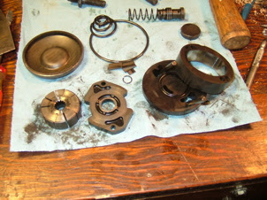
Here are the parts that you've taken out so far. The lock ring, pressure plate, spring that holds the pressure plate against the lock ring, magnet, and pressure relief valve.

saginaw power steering pump parts
Left, pressure plate; center, lock ring, pressure plate spring,
Top left: stud, top right: pressure valve and spring, magnet
Inside, you'll see the pump assembly held in with a couple pins. The assembly is made up of a front and rear cover, sandwiching the eccentric housing and the vane and rotor assembly. 

IMPORTANT NOTE BEFORE YOU REMOVE ANYTHING ELSE: Find the arrows on the eccentric housing, and note whether they are positioned at the front or the back of the power steering pump. You can install the housing in the wrong way.

If you do, when you reinstall in your vehicle, you will find it extremely hard to turn the steering wheel--the pump is actually fighting against you instead of assisting you. Ask me how I know!

There are many little steel vanes that slide in and out of slots on the rotor. First, remove the small lock ring on the pump shaft holding this assembly in. And, when you tip the pump upside down to tap out this assembly be careful you don't lose any parts. When you're done you'll have a bigger pile of parts.

saginaw power steering pump parts
Disassembly of Power Steering Pump section
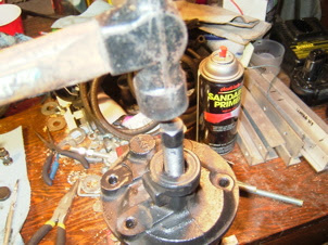
Finally you'll need to tap the shaft (below) from the front.

saginaw power steering pump rebuild
Tap out shaft
You'll have this pile of parts, which now includes the pump shaft and lock ring.

saginaw power steering pump parts
Power steering pump parts now including shaft
Finally everything is disassembled. Now it's time to replace all the remaining seals and reassemble. 

Power Steering Rebuild

saginaw power steering pump rebuild
Remove PS front seal with seal removal tool or screwdriver
Now, remove the front seal. You can also drive out the shaft bushing and replace that.

Replace the o-ring on the rear pressure regulator fitting (below). 

saginaw power steering pump rebuild o-rings
Replace pressure regulator o-ring
Clean the pump mechanism parts: the vanes, rotor, and rest of the assembly. Might as well oil them with ATF (or PS fluid) and reassemble them into the case with the lock pins. 

Once again, make sure the direction of rotation is correct.

Replace the large o-ring around the pump housing, and the two small and one medium o-ring on the back face (below). 

saginaw power steering pump o-rings
Add caption

PS Pump Reassembly

Reassembly is essentially the reverse of disassembly. Reassemble the pump mechanism into the reservoir, reinstall the studs, pressure valve, and fitting, etc. Reinstall the PS pump onto the vehicle, reinstall the pressure hose and return hose, fill the reservoir, and give it a try. 

If all goes well, it won't leak, and your power steering assist will be like new once again. Congratulations, you did it!

Basic Troubleshooting Tips

If it does leak, particularly around the large seal between the pump and reservoir, you might consider finding a different case at the junkyard and trying once more. That happened to me. The second time it worked great. Again if the power steering is fighting you and it's really hard to turn the wheel, you reversed the rotation of the pump eccentric housing. Time to do it all over again.

Even if you fail once or twice, in the long run, as you do this a few more times over the life of this and other vehicles, it'll get easier and you won't have to keep spending big bucks on rebuilt pumps.

Friday, August 10, 2012

On-Board Air Install

I thought I'd share everything I've done with my own OBA system to date in case it helps you out. The following is a logical diagram of the OBA system.


Hardware

Here's a diagram of the hardware layout. I'll highlight each of the main components in the following sections.


Compressors

FSJs came with York air conditioning compressors from the 70's through about 1987 or 1988. These are the go-to compressors for OBA primarily due to air flow but also because running them upright means they don't lose (much) oil. After about 1988, Chrysler switched over to a Sanden rotary compressor which are not good for OBA due to the way oiling works. But they're fine for AC.

Orientation

Normally the earlier York compressors came from the factory installed horizontally with the compressor's head on the left side of the vehicle but you can just as easily install them upright. I ran mine this way while it was still doing AC duties for a few years and it did great. How?

Take off the AC bracket, then unbolt the York from the bracket, relocate the studs from the side to the bottom, and reattach bracket to the bottom, and reinstall bracket. You may want to add some bracing as well as you won't be able to reuse the factory top brace.

Once installed vertically the compressor will (mostly) retain oil in the crankcase (the York is basically like a little engine but with a head specific to air compression). There's another conversion you can do to force it to retain all the oil, but I haven't done that yet. If/when I do, I'll let you know.

OBA, The Basic Parts

First off, let's talk about the overall system design. In TC's case, I wanted OBA for airing up tires after trail runs and I wanted a source of compressed air to run my ARB front locker (sssh, don't tell ARB because I voided the warranty by not using their $300 electric compressor). I also needed an air tank for both uses. Let's ignore the locker air system for now.

First you need fittings that convert your York to National Pipe Thread (NPT) fittings. You can source these from Kilby Enterprises, pictured below.

NPT adapter
If you add a tank, the first thing you want to do is make sure you have a popoff valve on the tank (pictured below). This is a very, very critical safety device that ensures you don't pressurize your tank beyond its limits.
Safety valve
How do you find the tank's pressure limits? Find out the maximum pressure rating when you get the tank first from eBay, or craigslist, or new from 4x4 shops. Then get a popoff valve, rated at or below the tank rated pressure, from the hardware store or an industrial supply / compressor store, or buy online at Kilby, Northern Tool + Equipment, McMaster Carr, Grainger, or various other places.

Unless you convert the York it is going to spit out a little bit of oil (less since it is oriented vertically) and you don't want that oil in your tires, do you? To prevent it, get a mini oil separator from your favorite hardware store. Mini because it'll be easier to find a place for.

Typical pressure switch
Kilby pressure switch
The other thing you need is a pressure switch (pictured above) that is matched to your system's pressure capacities. Let's say you have a 150psi tank, so you'll probably have a 150psi air safety valve, so you want your compressor to turn off before 150psi (well, at least I would think this would be best; depends on whether the pop-off releases above 150 or right at 150)

You can get these switches from hardware stores, McMaster Carr, Northern Tool, etc., or you can get a smaller, simpler one from Kilby. I got mine from an industrial supply shop. These switches are designed to turn on the compressor at a low pressure setting, and turn off at a high pressure. Ideally, the pressure switch should also incorporate a release / relief / let off valve. What this does is lets off pressure at the compressor when it is turned off. More on this in a moment. The small, simple Kilby switch doesn't provide this feature.

Many of the large clunky industrial type switches allow you to adjust the high pressure shut-off which I find very useful to match your system. The differential (the pressure difference between on and off) is usually fixed but some switches allow you to adjust this too, though I don't think that's so useful. The Kilby switch doesn't appear to be adjustable in any way.

With just the pressure switch, a few brass fittings, some air hose to run to the air tank, and a quick release fitting, you've got the hardware to air up tires. You can also use an air manifold from Kilby (right), Northern Tool, or McMaster Carr for a more compact, clean installation.

Pressure Relief

As suggested above, you really want to have a way to relieve pressure on the compressor side of things to ensure easy compressor startups and long life. Otherwise when the switch turns off the compressor it has to hold all that pressure it's stuffed into the tank.

Instead, you want a check valve between the pressure valve and air tank and a way to bleed off pressure between the check valve and the compressor. Install a fitting and copper pipe on the compressor side of the check valve, and run the pipe to the relief valve on your pressure switch. When the switch shuts off, it opens the valve to bleed air through the copper pipe. The check valve holds air pressure in the rest of the system. The check valve is available at industrial supply shops, possibly at hardware stores, and you might check Kilby. I had a friend get mine from Grainger but I'll bet McMaster Carr has 'em (and doesn't require commercial accounts).

Adding a Low Pressure Subsystem

ARB lockers require lower pressure than you would normally run to air up tires, around 90 psi versus 120-150psi. So what I did was to tack on an entire low pressure subsystem to run the locker. That started with a compact pressure regulator you can get at Harbor Freight, or a chain hardware store. As long as the rest of the system is above 90psi the regulator will hold 90 all day long.

Worth keeping in mind, the ARB solenoid doesn't use 1/8" NPT. It uses 1/8" British Standard Pipe Tapered (BSPT). They're close but why not be exact. So you need a male to male fitting that converts from 1/8" NPT to 1/8" BSPT. If I'm not mistaken I got mine from McMaster Carr but you might want to Google around. So with the conversion you attach your solenoid and then plumb your ARB as per normal. When you power up the system, set your regulator to deliver 90psi. The regulator I got has a little gauge which is of course vital to making sure you get the pressure set right.

Electrical


You don't have an OBA system unless you have a way to control it electrically. The York compressors have a clutch that is engaged by sending +12V to the wire leading out from the unit. The pressure switch determines when the compressor should come on, that is, when pressure in the system is below a certain threshold. It also determines when to shut the compressor back off, when the upper threshold is reached.

But you want to have the ability to prevent the compressor from coming on at all, like when you're tooling down the highway. So you need a master switch that controls whether power is sent to the pressure switch in the first place. I used an ARB compressor switch and cover that I bought online. I thought it'd also be kind of nice to be able to have an underhood switch that would bypass the in-cab switch, and used an old DPDT toggle switch I had on hand. With the switch up, it turns the system on. Down defers to the in-cab switch, and center turns the system off (regardless of the in-cab switch).

The other electrical component that needs some wiring is the ARB air solenoid. Sending it +12V will open it, sending (hopefully) 90psi of air down to the differential. I used the ARB switch and cover that came with the ARB for this purpose. This and the other switch also need to be wired in parallel with your dash lights so they will be backlit with the headlights or parking lights on.

Where does the +12V come from? Both ARB and compressor should be powered from a switched source. You won't need to engage your ARB with the motor shut off. (If it stalls the key will still be in the run position and keep the locker engaged). The compressor clutch does no good if it is engaged with the motor off.

That's all for now, I'll finish up this article later.

Thursday, August 9, 2012

FSJ V8 Vacuum Routing

FSJ vacuum routing can be daunting to look at. Here's a quick rundown on routing for a mid-80's FSJ. Different model years used slightly different vacuum routing. See links at the bottom for a great site on vac diagrams for various model years.

Here's a large, hi-res diagram that is color coded to make it a little easier to distinguish between different vacuum sources. We'll dissect this thing piece by piece to make it easier to figure out.


Color-coded FSJ Vacuum Diagram for V8
There are a few minor differences between 85 and 86+ so here is an underhood vac diagram for 88 to reference for some stuff. Big thanks to Tom 'Oljeep' Collins for putting all these diagrams (and more) in one place!

88_FSJ_Vacuum_360.jpg

Let's step through the diagram to understand it better.

Vacuum Spark Advance

Spark advance is based on engine temperature as follows:

  • Under 160°F: mixture of manifold and vacuum advance
  • Over 220°F: manifold vacuum
  • Otherwise: ported vacuum

Knowing how the system behaves, let's trace the vacuum hoses from the distributor backwards.

The distributor vacuum hose traces back to the middle "output" port of the HDC CTO (Coolant Temperature Override) vacuum switch; that's the CTO on the thermostat housing. The middle of these type of CTO's is the "output" and based on temp, it switches between one of the two "inputs".

Spark advance vacuum routing


If the engine is too hot, above 220°F, it draws from manifold vacuum. Why? Because the theory is that this will bump up the idle and thus cool the engine down. Does this work? I doubt it.

Hot (>220°F) spark advance vacuum routing
If the vehicle is below 220°F, the "input" selects the Spark CTO switch's "output". The Spark CTO selects a vacuum source for cold or warm operation.

Normal spark advance vacuum routing
If the vehicle is warm, above 160°F, it simply selects ported manifold vacuum as the source for vacuum advance. Easy enough.

Normal temp, spark vacuum advance routing
When the engine is cold, below 160°F, the engine gets a mix of manifold and ported vacuum. The device that controls the vacuum signal during cold operation is the Non-Linear Vacuum Regulator. It basically just limits the vacuum signal going to the vacuum advance.

Cold temp, NLVR vacuum routing
Ok, so that takes care of the entire spark advance system.

Simplify Vacuum Advance Routing

Simple FSJ Vacuum Routing
You can simply all this if you so choose. First, remove the NLVR. Where it "taps into" a vac line, replace the T with a straight adapter or run new line.

What you end up with is the Spark CTO gets Manifold vacuum when cold, and ported when hot. This is how the earlier model FSJs were "wired".

You can also ditch the high temp (HDC) CTO. Run the Vac advance line direct to the Spark CTO "output" (middle). Remove the T fitting for the HDC CTO that goes to manifold and replace with straight or run new line.

Make sure you preserve a manifold vac signal going to the power valve!! (or else it will always be on!) This greatly simplifies the spaghetti. You now have one CTO where you used to have a 2 CTOs and an NLVR.

EGR Vacuum Control Routing

Let's move on to the the EGR system. It's operating is also based on temperature. If the EGR is enabled, it only operates on part throttle load. Not full throttle, and not lightly loaded part throttle or idle. The EGR is only enabled when both the engine coolant temperature and incoming air charge are warm.

Starting at the EGR itself, it is ultimately sent a ported EGR signal from the carburetor. But that signal only makes to the EGR if the air drawn into the motor is warm, as determined by a sensor on the side of the air cleaner housing called the TVS (Thermal Vacuum Switch). When it's warm, it lets vacuum through. When it's cold, it blocks vacuum signal, disabling the EGR.

EGR Vacuum Control
The signal also won't make it to the EGR if the engine coolant temperature is too low, as determined by one half of the Dual CTO. It's just like the CTOs used in spark advance, but they packaged two CTOs in one device.

Also, there's often a delay valve inline between the EGR and the TVS so that the EGR comes on gradually after a short delay. However, one service bulletin fix for pinging is to remove this. So you may not have it. That's the EGR system.


AIR System Vacuum Routing

Let's look at the AIR system. AIR stands for Air Injection Reaction and it injects air into the exhaust manifolds under certain conditions to oxidize unburned fuel and at other times into the catalytic converter to aid its operation.

The source of this air is the AIR pump. The air goes to a diverter valve (AIR Control Valve) that sends air to the manifolds or to the catalytic converter, based on engine temp as well as engine load.

Under acceleration the signal goes away which diverts air to the cat (to address the vehicle running rich). When cold or under cruise, the air is sent to the manifolds to further oxidize the outputs of combustion.

On 86+ FSJs (see below) the AIR Control Valve also includes a valve to allow or shut off the flow entirely; when the vehicle starts up, it turns on the valve with manifold vacuum. During acceleration, when manifold vacuum drops, the reverse delay keeps the system on.

86+ FSJ Air Control Valve Vacuum Routing
The air control valve diverter is controlled by manifold vacuum. When the vehicle is cold, air is sent to the manifolds, when hot, to the catalytic converter, but only under heavy load (low manifold vacuum).

AIR system vacuum routing


And that's it for the AIR system.

Thermal Air Control

The Thermal Air Control (TAC) system operates the valves on your air cleaner snorkle to regulate the intake air temperature.

When the engine is on, manifold vacuum is held and applied to the main valve in the snorkle; when the engine is shut off, the valve closes, helping to prevent evaporation of fuel, presumably.

A TAC sensor, in essence a thermal vacuum switch, tells the second valve to select hot air drawn across the exhaust manifold through the silvery corrugated downpipe that you probably lost years ago or, once the engine is warm, from cooler outside air, through the corrugated black tube going to the front of the engine bay near the battery if you didn't lose that too.

TAC vacuum routing
The check valve holds vacuum on the main valve motor (evaporative system motor) to keep the valve open at all times while the engine is running.


Vacuum Brake Booster

And that's pretty much it. You also have a giant vacuum tube going from the front manifold brass fitting to the brake booster.

Heater and 4x4 Control

There's supposed to be a vacuum signal going to the round ball -- a vacuum reservoir for your 4x4 and heater.

Cruise Control

And also vacuum to the black coffee can on the passenger side-- your cruise control reservoir. Those aren't shown on the diagram.

PCV, Bowl Vent, Gas Tank Vent

The diagram above shows your PCV (Positive Crankcase Ventilation) routing, bowl vent and purge valve routing, and gas tank vent routing. The carbon canister opens up to allow the carburetor to draw fuel vapors in by way of the purge valve, operated by ported vacuum. Under part throttle heavy load, the carburetor sucks some fuel vapor out of the canister.

PCV, Bowl Vent, Carbon Canister

Simplification

Added 01/04/08
Thanks to Strider on IFSJA BBS for providing the graphic of a simplified spark advance. I did this on my rig some time ago for testing, and it seems to work fine. Basically you're eliminating the 2nd CTO and the NLVR. This really cleans up the spaghetti.

Further Information

The best collection of FSJ vacuum diagrams has to be Tom 'Oljeep' Collins' website, hands down. He also has great electrical schematics for various years and myriad other reference material.

Wednesday, August 8, 2012

Delco Alternator Rebuild Guide

Delco-Remy 12SI Alternator
Here's a DIY guide to rebuild your failed your Delco alternator requiring only basic mechanical skill, a few tools, a cheap rebuild kit, an hour or less, and these instructions.

For more information on identifying alternators, this article by Mark Hamilton is very well done.

Parts and Tools

Pictured below is a classic Delco (Delco-Remy) aka GM, Volvo, Saab, Jeep alternator, model 12SI, along with the tools you'll need for the rebuild. From left to right: hex key set (smaller hex key for holding brushes), needle nose pliers, combination wrenches, 1/4 drive extension, socket, and 1/4 drive wrench for removing housing bolts and internal bolts, flat head screwdriver to pry apart housing, and permanent marker.

Delco 12SI Alternator and tools for rebuild
Here's the alternator repair kit I bought from Autozone. Your rebuild kit should provide you with new brushes, a new voltage regulator, new diode package, a couple springs for the brushes, a thin metal wire, and a front bearing/bushing. Time to replace everything and reassemble.

The alternator kit I used from Autozone
You can pick up Delco-Remy 12SI alternator rebuild kits for under $15 at any chain auto parts store or even online. Here's a kit for 56A, 78A, and 85A alternators (P/N GMA01) from partsamerica.com.

Note: P/N GMA02 is for the 94A version. Another example is the Amazon alternator listed at the top right of this article (should work with the lower current 12SI).

Note: You might want to click the compatibility charts to make sure it will work with your vehicle.

Opening the Alternator

You'll start by marking the housing so you know how the two halves are supposed to go together. Called "clocking", these alternators can be put together so the mounting bracket on the front half and the field plug on the back half can be oriented at any position.


After marking, remove the four long hex head bolts that hold the two halves of the housing together using the right 1/4"-drive socket, extension, and ratchet wrench.


Remove hex bolts from rear of alternator to begin opening the case

Next, use a screw driver to pry the housing halves apart at the pry points shown and pull the case halves apart.

Pry alternator halves apart with a screwdriver

Now that you've got yourself two halves of an alternator take the back half and stare into it and you should see something very similar to the following.

Back half of the alternator with diodes, brushes, regulator identified
Below is a detail picture of the assembly that holds the alternator brushes. Brushes oftentimes are the main thing that wear out over time in an alternator.

Brushes

Remove Regulator and Brushes

Start by taking out the the bolts holding the regulator and brush housing and remove both. Throw away the regulator but keep the brush housing.

Remove the 3 bolts holding the regulator and brush assembly
Note that there is something that looks like a threaded rod that is held down by two bolts that hold down the regulator and diode contact. Remember where this goes (refer to the pictures above). I think this is a resistor.

Old regulator, left; brush housing, right
Now remove the brushes but don't lose the springs, yet. Throw the old brushes away.

Match the old springs inside the housing to one of the new springs in your alternator repair kit. Install the springs in the housing and throw away the old ones.

Find the long thin piece of metal wire included in the repair kit. It holds the brushes in place until the alternator is reassembled.

There is a hole in the back of the alternator that you can use to pull this wire out, once you've reassembled both halves. If you don't do this, the brushes pop out of the housing and you can't insert the shaft.

Install the new brushes in the housing and force them into the housing until you can slide the thin metal wire through the hole in the housing and brushes.

Retaining brushes with thin metal wire provided in kit

Replace the Diode Rectifier

The diode rectifier pictured below is removed by taking out three additional bolts.

The diode rectifier on the left is held by three remaining bolts
Throw away the rectifier and replace it with the new one in your repair kit. Reinstall it in place and tighten down the three bolts on the left.

Replace the Regulator and Brushes

Now install the regulator and brush housing along with the threaded rod resistor thingy with the three bolts that hold it in place. One of those three bolts also holds down a leg of the diode.

Look at the back of the alternator and be sure that you can see and grab the thin wire holding the brushes.

Grease the Rear Bearing

The rear bearing on these alternators isn't sealed. Unless it's shot, throw some grease on it. I used axle bearing grease.

Pic 4. Brushes held by wire, greased rear bearing, final regulator bolt

Reassemble the Alternator Case

Put both alternator case halves together, aligned with the mark you made, and install the rear hex head bolts that hold the case halves together.

Replacing the Front Bushing

One thing I have not attempted is to replace the front bearing. However, I have had one of these go out before and they are included in the rebuild kit.

My educated guess is that the process is as follows: Use an impact wrench to remove the pulley and cooling fan, and slide the shaft out through the back of the housing. Use a bearing/seal driver to punch the bearing out. If I get around to doing it myself I'll post up definitive instructions.

Congratulations!

Congratulations! You're all done and you saved yourself a pretty good chunk of change on a new alternator by spending a little time. This rebuild is pretty hard to get wrong so there's a good chance when you test it, everything will be a-ok.

If you do a lot of back country driving, the last thing you want is to have your alternator die on the trail so how about keeping a spare rebuild kit in your getcha-back-box? Or get a broken alternator from a friend for free and rebuild it as a spare.

Thanks, hope this article helps! If so, please share it with your pals.