
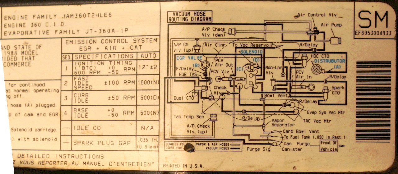
Here's a large, hi-res diagram that is color coded to make it a little easier to distinguish between different vacuum sources. We'll dissect this thing piece by piece to make it easier to figure out.
 |
| Color-coded FSJ Vacuum Diagram for V8 |
88_FSJ_Vacuum_360.jpg
Let's step through the diagram to understand it better.
Vacuum Spark Advance
Spark advance is based on engine temperature as follows:- Under 160°F: mixture of manifold and vacuum advance
- Over 220°F: manifold vacuum
- Otherwise: ported vacuum
Knowing how the system behaves, let's trace the vacuum hoses from the distributor backwards.
The distributor vacuum hose traces back to the middle "output" port of the HDC CTO (Coolant Temperature Override) vacuum switch; that's the CTO on the thermostat housing. The middle of these type of CTO's is the "output" and based on temp, it switches between one of the two "inputs".
 |
| Spark advance vacuum routing |
If the engine is too hot, above 220°F, it draws from manifold vacuum. Why? Because the theory is that this will bump up the idle and thus cool the engine down. Does this work? I doubt it.
 |
| Hot (>220°F) spark advance vacuum routing |
 |
| Normal spark advance vacuum routing |
 |
| Normal temp, spark vacuum advance routing |
 |
| Cold temp, NLVR vacuum routing |
Simplify Vacuum Advance Routing
 |
| Simple FSJ Vacuum Routing |
What you end up with is the Spark CTO gets Manifold vacuum when cold, and ported when hot. This is how the earlier model FSJs were "wired".
You can also ditch the high temp (HDC) CTO. Run the Vac advance line direct to the Spark CTO "output" (middle). Remove the T fitting for the HDC CTO that goes to manifold and replace with straight or run new line.
Make sure you preserve a manifold vac signal going to the power valve!! (or else it will always be on!) This greatly simplifies the spaghetti. You now have one CTO where you used to have a 2 CTOs and an NLVR.
EGR Vacuum Control Routing
Let's move on to the the EGR system. It's operating is also based on temperature. If the EGR is enabled, it only operates on part throttle load. Not full throttle, and not lightly loaded part throttle or idle. The EGR is only enabled when both the engine coolant temperature and incoming air charge are warm.Starting at the EGR itself, it is ultimately sent a ported EGR signal from the carburetor. But that signal only makes to the EGR if the air drawn into the motor is warm, as determined by a sensor on the side of the air cleaner housing called the TVS (Thermal Vacuum Switch). When it's warm, it lets vacuum through. When it's cold, it blocks vacuum signal, disabling the EGR.
 |
| EGR Vacuum Control |
Also, there's often a delay valve inline between the EGR and the TVS so that the EGR comes on gradually after a short delay. However, one service bulletin fix for pinging is to remove this. So you may not have it. That's the EGR system.
AIR System Vacuum Routing
Let's look at the AIR system. AIR stands for Air Injection Reaction and it injects air into the exhaust manifolds under certain conditions to oxidize unburned fuel and at other times into the catalytic converter to aid its operation.The source of this air is the AIR pump. The air goes to a diverter valve (AIR Control Valve) that sends air to the manifolds or to the catalytic converter, based on engine temp as well as engine load.
Under acceleration the signal goes away which diverts air to the cat (to address the vehicle running rich). When cold or under cruise, the air is sent to the manifolds to further oxidize the outputs of combustion.
On 86+ FSJs (see below) the AIR Control Valve also includes a valve to allow or shut off the flow entirely; when the vehicle starts up, it turns on the valve with manifold vacuum. During acceleration, when manifold vacuum drops, the reverse delay keeps the system on.
 |
| 86+ FSJ Air Control Valve Vacuum Routing |
 |
| AIR system vacuum routing |
And that's it for the AIR system.
Thermal Air Control
The Thermal Air Control (TAC) system operates the valves on your air cleaner snorkle to regulate the intake air temperature.When the engine is on, manifold vacuum is held and applied to the main valve in the snorkle; when the engine is shut off, the valve closes, helping to prevent evaporation of fuel, presumably.
A TAC sensor, in essence a thermal vacuum switch, tells the second valve to select hot air drawn across the exhaust manifold through the silvery corrugated downpipe that you probably lost years ago or, once the engine is warm, from cooler outside air, through the corrugated black tube going to the front of the engine bay near the battery if you didn't lose that too.
 |
| TAC vacuum routing |
Vacuum Brake Booster
And that's pretty much it. You also have a giant vacuum tube going from the front manifold brass fitting to the brake booster.Heater and 4x4 Control
There's supposed to be a vacuum signal going to the round ball -- a vacuum reservoir for your 4x4 and heater.Cruise Control
And also vacuum to the black coffee can on the passenger side-- your cruise control reservoir. Those aren't shown on the diagram.PCV, Bowl Vent, Gas Tank Vent
The diagram above shows your PCV (Positive Crankcase Ventilation) routing, bowl vent and purge valve routing, and gas tank vent routing. The carbon canister opens up to allow the carburetor to draw fuel vapors in by way of the purge valve, operated by ported vacuum. Under part throttle heavy load, the carburetor sucks some fuel vapor out of the canister. |
| PCV, Bowl Vent, Carbon Canister |
Simplification
Added 01/04/08Thanks to Strider on IFSJA BBS for providing the graphic of a simplified spark advance. I did this on my rig some time ago for testing, and it seems to work fine. Basically you're eliminating the 2nd CTO and the NLVR. This really cleans up the spaghetti.
Really good information here. I do have a comment regarding your vacuum advance section, however.
ReplyDeleteAs I understand it, the reason the engineers at AMC (and many other domestic manufacturers at the time) wanted specific vacuum timing advance characteristics were for the following reasons:
Cold operation: "Mixture of manifold and ported vacuum" or essentially "high partial advance" as compared to straight manifold vacuum which would net full advance or straight ported which would allow less advance---when the engine has not yet reached steady state operating temperature it is crucial to keep combustion temperatures higher in order to get heat to the piston and valvetrain quickly to reduce wear and blowby (which is why they let some manifold vacuum creep in). Ideally, we would want more advance for this purpose as the leaner idle mixtures need more advance to create the higher combustion temperatures and better timed peak cylinder pressures, but higher combustion temperatures result in higher NOx levels in tailpipe emissions...so they implement this strategy to reduce combustion temperatures slightly (and thus NOx emissions) while also allowing some of the unburned fuel to make it into the hot exhaust manifold wherein the air pump injects fresh air to post-combust fuel to ensure rapid burn of the remaining mixture which therefore reduced unburned hydrocarbons as well. Efficiency is lost, but emissions are slightly improved. This is why the air pump diverts to the manifold at colder operating temperatures.
Warm operation: "Ported vacuum" or essentially "zero advance at idle and partial advance at cruising speed" as compared to straight manifold vacuum which would allow for full advance at idle and steady state operation, only to drop off as the engine is under acceleration and full throttle applications---when the engine is at operating temperature, the stock configuration gives partial vacuum advance which still balances between reducing combustion temperatures and NOx emissions, but now the entire exhaust (including the catalytic converter) is warm and the air pump is injecting air into the catalytic converter so that the CO2 made from the light-off of unburned hydrocarbons can most effectively be catalyzed. Again, we are reducing emissions but also reducing efficiency by not allowing for optimum spark timing which, in turn, reduces combustion temperatures by not allowing leaner mixtures to optimally burn which reduces peak cylinder pressures which reduces mileage and performance.
ReplyDeleteReally hot operation: "Straight manifold vacuum" or "full advance at idle and low-load conditions but loss of advance as manifold vacuum drops under acceleration as mixtures become richer and quicker burning" ---when running less than optimal advance (such as discussed above) and allowing unburned fuel to make it to the exhaust to burn outside of the engine...this greatly increases exhaust gas temperatures and the cast iron manifolds radiate tons of heat into the cylinder head water jacket. The engineers probably realized that the only way to bring EGT and thus coolant temperatures back down at the extreme was to give the engine what it actually wants---screw NOx emissions at that point, nobody is going to go emissions testing after towing a trailer in the middle of summer anyhow, right?
What you mentioned about bumping up idle is part of the equation, but also bringing EGT down really helps the coolant carry less unnecessary heat away because at higher advance (and higher combustion temperature) more heat is being carried away in the exhaust gas charge rather than being generated in the manifold when exhaust gas velocity is low (post valve closure) and heat soaking the manifold.
My conclusion? If you aren't worried about emissions and running the air injection pump system...just run straight manifold vacuum to the distributor and set base timing accordingly.
If you are still running the air injection system, the setup you proposed for simplifying the mess of hoses will work just fine....but the HDC vacuum switch does likely have some added benefits in more extreme operation conditions where the emissions system should essentially shut off and let the engine do what it wants.
Have a 87 Grand, My mechanic took took all the smog stuff off. I put it all back because my heater would not blow thru defrost or floor even though hoses hot and fan ran. One thing is my air pump needs replaced but i do not know if any of the vacuum for the smog has anything to do with the heater not allowing air in cab.
ReplyDeletequestion, does the air pump have anything to do with the heater vacuum? My mechanic removed all the smog stuff while putting in a new master cylinder and did not put it back and now my fan runs but no air in cab. I put it back on only to find out the air pump is bad. Is that the issue?
ReplyDeleteHave a 87 Grand, My mechanic took took all the smog stuff off. I put it all back because my heater would not blow thru defrost or floor even though hoses hot and fan ran. One thing is my air pump needs replaced but i do not know if any of the vacuum for the smog has anything to do with the heater not allowing air in cab.
ReplyDeleteThanks for the information! You saved what little hair I have left from being pulled out!
ReplyDeleteHave an 88' Grand Wagoneer. Comparing the before mentioned sticker, mine is a JAM5.9T2HLE8, 360 CID, JT-5.9F-1P. What is the difference? Is it the carburator and will the simplification still work for me?
ReplyDeleteHi, the simplification will work for your 88. It uses the same Motorcraft 2150 carburetor and similar if not identical vacuum and emissions equipment.
Delete